
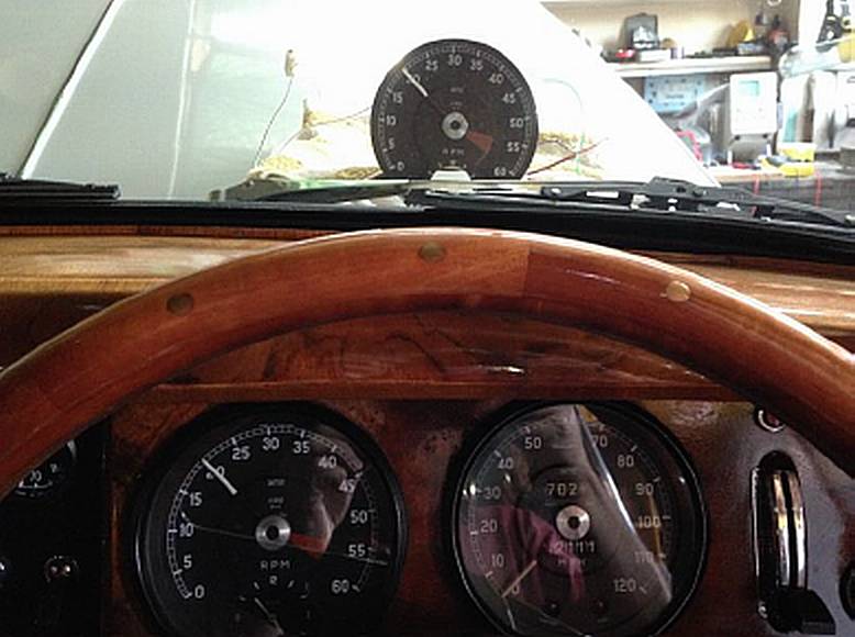
 Some years back I read an article on the AC generator driven Tachometers fitted to early E types, Mk2’s, S types and Mk 10’s. The story goes that the permanent magnet inside the ‘generator’ on the back of the head loses strength with age and produces lower voltage which in turn causes the tachometer to read lower than the actual engine speed.
 A solution to the issue was developed by Dave Rawle in England around 2008 with a circuit to count the pulses from the generator instead of the voltage. I believe Dave no longer makes these units, but at the time published pictures, detailed schematic, and even an accurate mask to etch the circuit board.
Recently I thought I was having an issue with my tacho generator and concluded this circuit is within my abilities to manufacture.
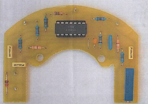
 First thought to mind – if it’s counting pulses, why not count the ignition pulses (like every other Tacho) and eliminate the AC generator completely? With the help of the techs at work I came up with an altered circuit to suit
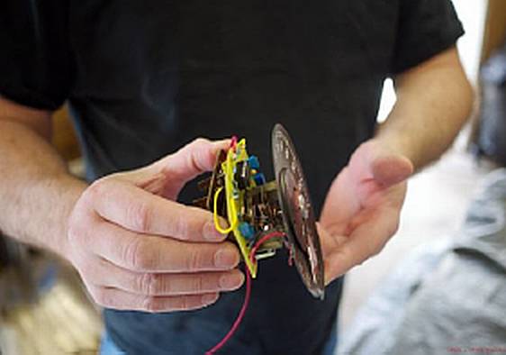
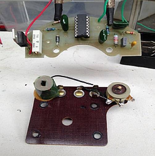
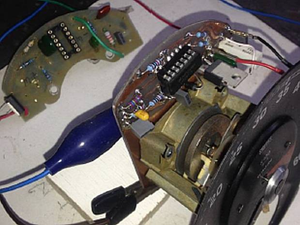
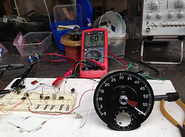 The ‘new’ board is mounted in front of the old one (same as Dave’s unit), so the old inductor and rectifier have to be removed to make room. After sourcing a suitable donor tacho to experiment with, the new circuit is connected and fed a signal from a ‘rigged up pulse generator’ to adjust the calibration at various increments (Like I was going to rev a car at 6000rpm while I fiddled tiny little screws with my big fat fingers!).
 For a final check, it’s connected to the car to see how it responds to real life ignition noise & voltages (which at first it didn’t!) – note, by this time I had already sorted my Tach problem and it was working perfectly ok.
Now that the concept has been proven, it’s time to review the bad bits The biggest problem is that the face has to be disturbed to mount the new board (something I would rather not do!).
 Second issue is the position of the trimming adjustment which means it can only be done with the movement removed from the case.
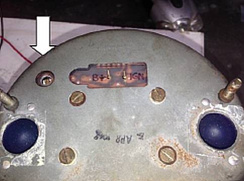 Prototype “Mk2” – has both the tracks and the components on the same side, so it can be attached to the rear of the movement, (completely replacing the original) and with the trim adjustment accessible from the rear through one of the original holes.
Where to next? After discovering 100 new ways to make it NOT work – Probably nowhere! (Remember, I fixed my tacho earlier) – Maybe “Mk3” with the voltage stepped up so it can simply connect to the original gauge terminals without disturbing anything at all. The tech’s say it just a ‘simple charge pump’ (need about 30 volts like the original AC generator), but their idea of ‘simple’ is usually a universe away from mine.
If anyone is interested, I did print off spare etching masks (in case of oopsies) and have bits to make another one, or if would like a copy & schematic to have a go at it themselves – get in fast – I have a habit of forgetting where I put stuff these days!
– Grant Rodman
![]()