
Heater Core Replacement
Series 1,2,3 XJ Sedans and early XJS models
This write up covers the removing and replacing a heater core assembly “the easy way” rather than removing the complete air blend box assembly which is a very big job. (refer to my write up on this in the Feb/Mar 2016 issues of Jaguar Torque.)
The above models are fitted with the Delanaire Mk-2 system which the following write up covers. First disconnect a battery terminal for safety reasons then proceed to remove both heater hoses from the heater pipes that protrude through the fire wall into the engine bay. Next you need to remove the coolant from the heater assembly. They don’t hold that much coolant maybe a one and half cup full’s at the most, but if spilt inside the vehicle it makes a mess.
The best and cleanest way to remove the coolant is to place a length of PVC clear vinyl tubing over one heater pipe (the outside diameter is 9/16” – 14mm) and have a small container ready to catch the coolant coming out of the tubing. Next you need an air compressor. You place the air outlet over the other pipe and gently blow out the coolant via the tubing into the container.
Next step is to remove the cover below the glove box. Next remove the glove box lid and glove box compartment. You can also remove the left hand side lower air outlet cover if need be. Removing the glove box compartment gives you access to the heater assembly which is fitted into the left hand side of the air blend box. At this point, you will see that the heater assembly is held in the air blend box by an outer end cover which is held in place with 6-8 small screws.
Next step is to cut both heater pipes just on the outer side of the end cover plate. This is best done using a small 240 volt grinder with a small 40-50mm diameter disc. Mark one of the pipes so you don’t get them mixed up when you are reassembling them, loosen the two clamps holding the pipes to the outer edge of the air blend box and you can now remove the cut pipes from the fire wall via the engine bay. At this point, it’s best to take a photo with your mobile phone or do a hand drawing of this side of the air blend box showing wiring harness and terminals, vacuum control rod and holding bracket, return springs and levers, as these items need to be removed to allow you to remove the end cover plate. It’s also best to mark the position of the levers and control rod positions with a marker pen before you remove them, as this makes it easy to reinstall in the correct position.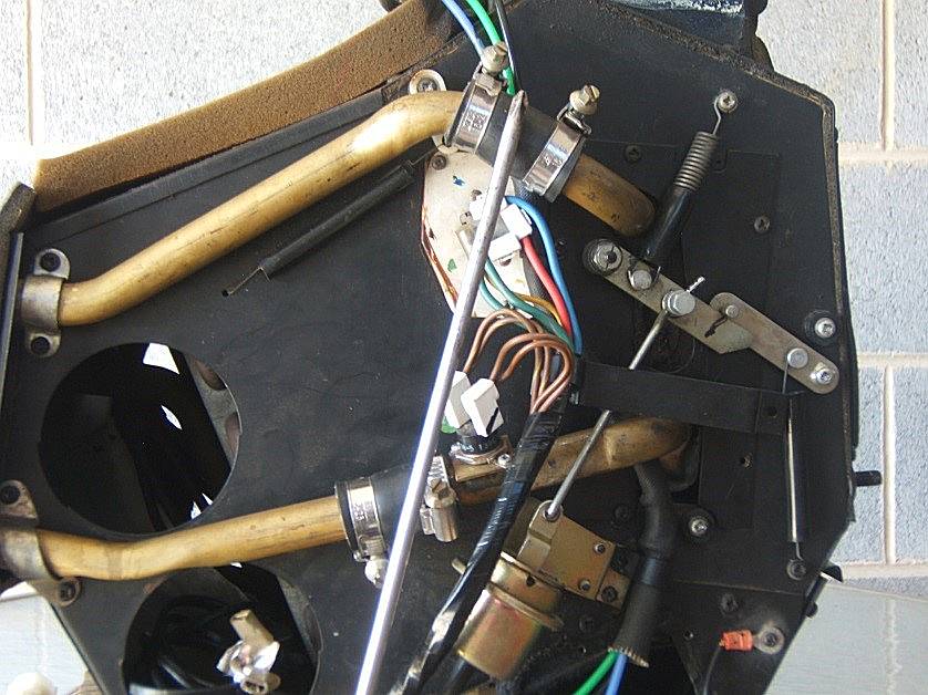
The cut pipes and hoses, colour coded wires, marked wire on the heat sensor switch, marked lever and control rod, the end cover plate with the small screws, and the outer pipe clamps.
(Click image to enlarge)
The wiring harness has four wires that are colour coded to their terminals which makes it easy when reinstalling. At this point, you also need to remove the two wires that are connected to the heat sensor switch which is mounted on one of the heater pipes, mark one wire and terminal with a black maker pen which makes it easy when reassembling, next remove the vacuum control rod and bracket, return springs and one lever.
Next step is to remove the small screws that hold the end cover plate to the side of the air blend box, it’s best to use a magnetic tipped Phillip’s head screw driver as its very easy to drop the small screws down the side of the air blend box and floor tunnel when removing them, if this happens get a small flexible handle magnet to retrieve them. Once all screws are removed you can pass the end cover plate over and off the shortened heater pipes to remove it, or simply leave it in position loose. You are now ready to remove the heater core assembly, hold the shortened heater pipes and wriggle the assembly loose within the air blend box and then pull it out of the air blend box, then pass it out through the hole where the glove box fits.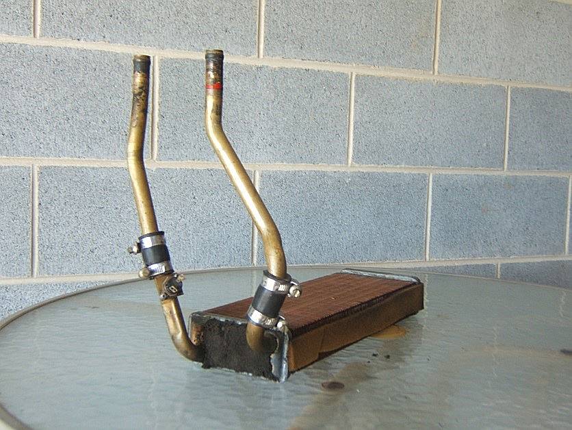
The heater core with cut pipe and hoses also form glued to the sides and inner end (not shown) and the remains of form piece on the outer end.(Click image to enlarge)
Note: At this point it’s worth mentioning that with the Delanaire Mk-2 system, the heater core and pipes are a single unit (hence the reason to cut the pipes to remove the heater core). On later models of the XJS the heater pipes are bolted to the heater header tank with a gasket in between and can be removed without the need to cut them. It’s a much better design when it comes to replacing a heater core.
There are two options when you order a new heater core assembly.
Option 1 Simply order a new standard unit and cut the pipes off in the same position as you did on the old unit.
Option 2 Send you old unit away to a supplier and have them remove both end tanks and reinstall them onto a new heater core.
In my case, I ordered a replacement standard unit from Spiteri’s in Melbourne. It came with approx 50% less fins than the original unit (more fins = more heat) but it came with new form glued around two sides and the inner end, the form stops metal to metal rattles within the air blend box.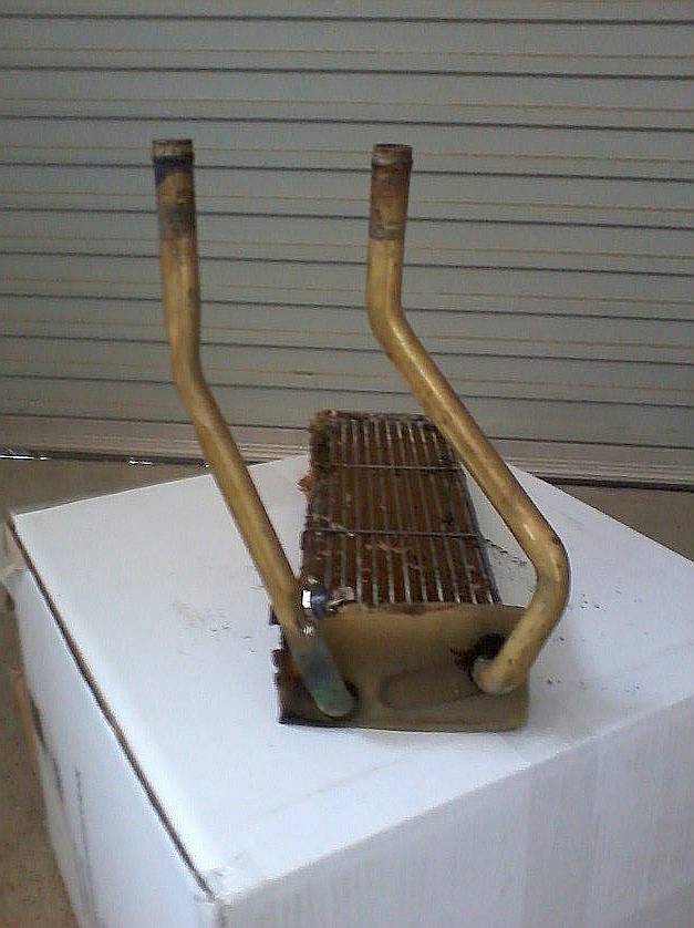
Standard heater core assembly.
Notice the form piece around pipes on the outer end.
(Click image to enlarge)
NOTE: You will not be able to source a replacement heater core in Australia with the same number of fins as the original units to my knowledge. The suppliers will tell you that they will be the same but I found this not to be true.
Reinstalling the replacement unit
Before you reinstall the replacement unit you need to file the edges smooth on the cut heater pipes and also purchase 100mm length x 14mm (9/16”) inside diameter heater hose and cut it in half, 2 x pieces 50mm long, and 4 hose clamps to suit.
Insert the hoses onto the cut off heater pipes half the hose length 25mm and install a hose clamp on each. Refit these two pipes via the cabin through the loosened pipe retaining brackets on the outer edge of the air blend box and through the holes in the fire wall. You may find it easier to remove the brackets before installing the pipes then refit the brackets after you have installed the pipes, at this point make sure that you have the pipe that you marked before you dismantled in the correct position.
Fit the two remaining hose clamps over the end of the hoses and just slightly tighten them so they don’t fall off. You can push the pipes as far forward as you like at this stage as the hose that you have fitted to the pipe won’t go through the hole in the fire wall. It’s only big enough to fit the pipe through.
Note: When fitting the 2 x 50mm lengths of heater hose to the pipes it pays to put some rubber grease on the pipe surfaces as this makes it a lot easier to slide the hose onto the pipes.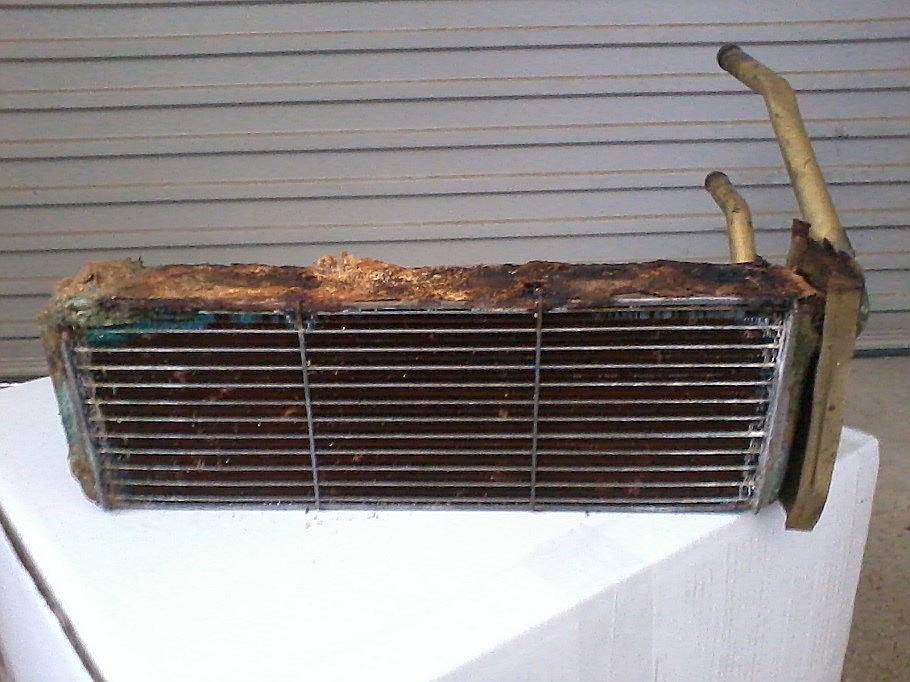
Signs of leaking core in top left of the core, shows as green in colour which is the coolant.
(Click image to enlarge)
Now you can install the replacement heater core assembly in the reverse way that you removed it. Before refitting the end cover plate, it pays to replace the small piece of form that is fitted over the inlet/outlet end tank. This will stop any end float of the core assembly and any metal to metal rattles that may occur between the header tank and end cover plate.
Now you can refit the end cover, using a magnetic tipped screw driver on these very small screws. Be very careful not to drop any. If this happens use a flexible handle magnet to retrieve them if possible.
With the heater core assembly now firmly in place you can now fit the short hose sections to the corresponding pipes on the header tank. Loosen the two slightly tightened hose clamps and rotate the outer section of pipe with the tightened hose clamps into a position where you can recheck the hose clamps for tightness later. Then slide the hoses onto the pipes on the header tank 25mm, then move the loose hose clamps into position and tighten. Now refit the hoses in the engine bay to the heater pipes and tighten the clamps.
Now you can reinstall the wiring harness and reconnect the four colour-coded wires to their corresponding terminals, heat sensor switch wires (remember that one of the wires you marked with a marker pen so you don’t install incorrectly) and the vacuum control rod and bracket, return springs and lever. At this point, it’s time to test the unit for any leaks that may occur around the new short hoses. Start the engine and run it up to operating temperature with the heater switched on or better still take the car for a short run.
Recheck for any leaks and recheck the four hose clamps for tightness and the two clamps on the heater hoses in the engine bay that connect to the heater pipes near the fire wall. If all looks ok, now reinstall the glove box compartment and lid, lower glove box cover and if you removed the lower air outlet cover on the tunnel, job is now complete and it’s a hold easier to do the repairs this way than removing the air blend box assembly which is a huge job (refer to my write up in the Feb/Mar 2016 Jaguar Torque)
NOTE: Regarding the photos that are included with this write up, it’s best if you view them online with the write up as they are in colour and show the items much better.
I hope this write up is of some value to members with these models that may require the heater core assembly to be replaced as winter is almost with us and that heater will need to be in good working order. If you find that you are losing a little coolant after a run with your car when you have had the air con / heater working, it may be a sign that the heater core is starting to leak.
Harry Bluett

![]()