
Rebuilding my in dash air conditioning unit on a XJ Series-3 V12
Part 2 – The Rebuild
Date work carried out: Sept/Oct/Nov 2015
I had already acquired a second hand evaporator unit and had it pressure tested ready to be installed. This slides into the air blend box below the 4 flaps and sits on metal strip about 10mm wide on each side. I also put strips of the 3mm self-adhesive form on, as it prevents any metal to metal rattles, also both ends of the evaporator have standard form fitted for the same reason. It’s not an easy job to keep the end form pieces in the correct position and at the same time slide the unit into position, then you can refit the outer cover.
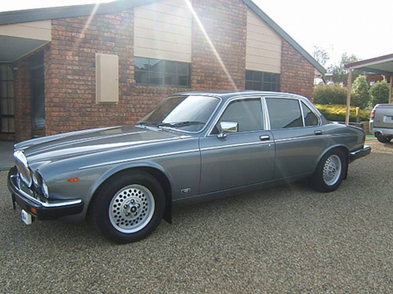
The imposing Daimler XJ S3 V12
Next job is to install the heater core which came with new form already glued to the outer edges. Spiteris advised that the new heater core would have the same number of fins in the core (not so), however the new core had about 50% less which makes the heater less efficient (more fins = more heat). On fitting the unit into the air blend box again, the heater pipes were not in the correct position, so this time I used a heat gun to position the pipes correctly, refitted the end cover plate, wiring harness and linkage lever, return spring and connecting rod. The connecting rod on the heater side is vacuum controlled and activates the flap the controls air flow when using demist. I also fitted the expansion valve assembly (TX valve) to the inlet pipe on the evaporator as it will fit through the hole in the fire wall and is easy to do rather than fit it on later which is a very hard job to do on a V12 engine. Apart from checking and double checking that all vacuum lines are connected correctly and wiring harnesses are in correct position, the air blend box is now ready to be reinstalled into the vehicle. Make sure that all the wiring laying on and around the tunnel, is out of the way before you attempt to install. I chose to get two other guys to help with installing this unit. One sits in front passenger’s seat, one in the driver’s seat and each one holds one side of the unit and as installing each guides the water drain pipes – one on each side into the holes in the tunnel, at the same time the third guy watches in the engine bay that the TX valve assembly passes through the hole in the fire wall without damaging it and also making sure that the mounting studs align with the holes in the fire wall as the two guys in the vehicle cannot see. This worked out very well and the unit was installed without any problems in 3-5 minutes. Next tighten the retaining nuts on the air blend box and reconnect the heater hoses and the inlet and return air con hoses to the TX valve assembly.
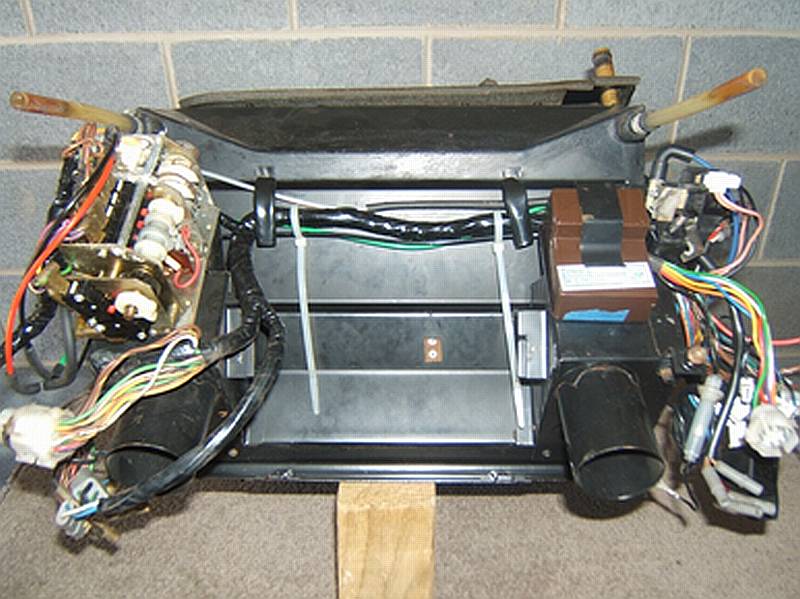
LEFT : Air blend box showing the servo motor (without cover on) on the left and the troublesome amplifier on the right (brown box).
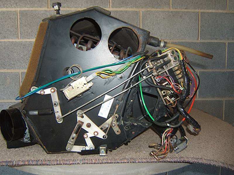
RIGHT : Air blend box side on showing two push rods connected to the servo motor.
Next job is to reinstall the dash board assembly, again it’s best that two do this job being very careful when moving in behind the steering wheel as it’s very easy to damage or even break the hazard switch, indicator and washer arms. Once in position it’s a simple job to refit the dash board mounting bolts, reconnect the wiring harnesses to the instrument cluster and glove box light wiring, plus the vacuum lines that operate the demist flaps.
Next job is to replace the dash pad. Before doing this, double check that all wiring to the dash board is correct, then reconnect the cabin temperature sensor and dash panel light wiring and finally retighten the retaining screws. Also, at this point you need to refit the air tubes to the air blend box. There are two on each side and they are like replacing a light bulb in your house, you align them with two slots in the air blend box and twist, job done.
Next job, and this is the big one, replacing the centre console assembly and getting your head around all the wiring, again it’s a lot easier if two do this job; with two guys one on each side. It’s best to take your time at this point making sure that all wiring is in the correct position. You also need to feed the fibre optic light lines back into position and reconnect them all to the centre cluster point. These feed the background lighting to the temperature, fan, light and ignition switches, plus the cold/hot slide lever that’s below the radio. Next you refit the air tubes from the fan motors to the tube pipes that are fitted to the sides of the air blend box, two on each side. Also, refit the air tubes that go to the rear seat passengers and reconnect all wiring harnesses. At this point, you should check and test at all lighting systems are working ok and also that the dash board lighting is ok and that your ignition switch is working as well.
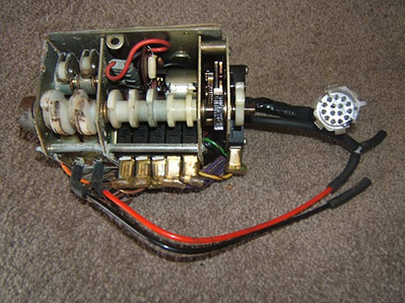
LEFT : The servo motor showing the cams and gears
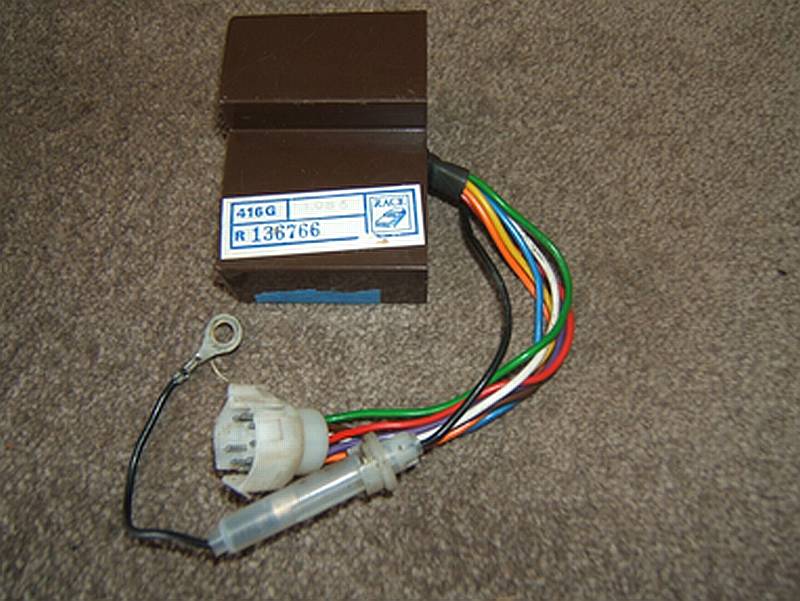
RIGHT : The troublesome amplifier
Next job is to position all the wiring and aerial lead for the radio/cassette, making sure that you place them on the correct rear side of the cradle box. If it’s on the wrong side you will not be able to insert the radio all the way back into position. Before final fitment it pays to test the radio first to make sure it’s working ok. Before you finally refit the centre console top which holds the window and sun roof switches and the panel that fits around the gear lever, centre glove box and lid plus the rear section of the centre console, it pays to double and triple check that all lighting systems are functioning correctly.
It also pays to mark all the window, lock out and sun roof switches as you dismantle as it makes it easier when you reassemble them. You can also test them as you reinstall them, working from the bottom to top switches as you go. That only leaves the forward console panels, outer air tube covers, fuse covers and dash pad end covers fit “but not yet”. The reason is the big start up test. If there is a malfunction somewhere you need to be able to see what is working and what is not, this leaves access to the three main electrical components, plus you can view the connecting rods for correct operation.
(1) the system controller (servo motor) and 2 connecting rods, on driver’s side.
(2) The relay box (3) amplifier and 1 connecting rod which are on the passenger side.
 I drove the car back to the air conditioning guy and had the air con system vacuumed tested again for any leaks, it was re-gassed and tested ok. As I travelled home I left the air con on at the coldest setting and it worked fine so I then switched to the hottest setting and found that the system was still blowing cold air and I couldn’t detect the servo motor making that whirring sound as it changes position. Upon returning home I lifted the bonnet to see if the water valve was working. This is easy to do, just remove the vacuum pipe from the water valve housing and the valve should close which mine did. I reconnected the vacuum line and the valve opened as it should, which meant that I had hot water going to the heater when I had the temperature set for the coldest setting. You can double check this by simply touching the pipes going to and from the heater core.
At this point after all this work frustration started to set in BIG TIME it was time to walk away and have a think for a while as to what could be wrong.
As mentioned earlier before I undertook this job, sometime before I had found the servo motor was not working so removed it and powered it up and tested ok. I then replaced the relay box and the servo motor came to life, at that point the air con wasn’t working only the heating side. After a while I realised that it only worked intermittently and could never work out why this was the case. I was reasonably confident that the servo motor and relay box were ok but you never know as items can fail at any time.
After my massive dose of frustration had subsided and I still didn’t know what my next move would be, I decided that a good old Google search might shed some light if I was lucky. I Googled “Jaguar Series 3 air conditioning fault finding”. I found a very good site www.kwecars.com. It lists all the major components and their operation, plus a list of the most common faults, the last one being (air con controls don’t work and cabin temperature never stabilise). It talks about the amplifier failing and is a very common fault on this air con model (Delanaire Mk-2 system). It goes on to say that an Australian company built a modern version of the amplifier for a short time but are now no longer available since 2012.
 I was able to source a spare servo motor, relay box and an amplifier from a friend of mine who had wrecked a Series 3. The amplifier though was a round unit about 100mm long x 30mm diameter and white in colour nothing like the standard units. Guess what – it was one of the Australian made units.
The amplifier is clipped onto the front left hand side of the air blend box just forward of the relay box and slightly inwards. It can be removed by first removing the relay box. I simply left the amplifier in place and unplugged the wiring harness and earth wire and plugged in the Australian made unit and connected up the earth lead. Then came the big test.
I started the engine up, set the temperature to the hottest setting, turned on the fan switch to auto setting and the system came back to life everything working as it should, the servo motor whirring away and connecting rods moving the flaps into correct position for heating. I then moved the temperature setting to the cold setting and once again servo motor started whirring again, changing the position of the cams and closing off the vacuum to the water valve which shuts off the valve, and connecting rods changing the flap positions for cold air. I then checked that the demist operation was working as it should. I then had one great sigh of relief that the system was working as it should. I simply tucked the amplifier inside the lower edge of the tunnel cover and left the original unit in place with its wiring harness and earth wire zip tired together out of the way.
I won’t bore you with fault finding on this system as it is quite sophisticated and embodies true climate control that is automatic temperature control and dehumidification.
I would suggest that owners of XJ series 1, 2, 3 & XJS models with this model air con (Delanaire Mk-2) unit that are having problems with its operation have a look at the web site as mentioned www.kwecars.com. At the top of the page, click onto the technical header and go down to “Jaguar air conditioning” and click onto it. It’s very good information plus you can print it off as a hard copy if you wish. It’s also worth looking at the next item down “air condition myths” which cover the types of gas that can be used. I hope that owners of the above models have found this write up of some interest and may shed some light on any air conditioning operating problems that they may have.
I intend doing a write up on how to go about replacing the heater core assembly the easy way for the same models in a later issue of Jaguar Torque.
– Harry Bluett
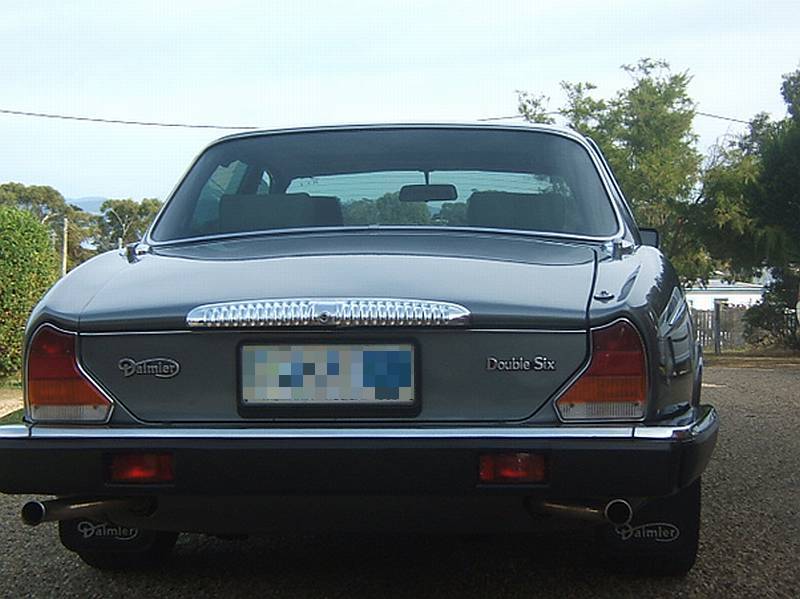
All done… time to drive off into the sunset.
![]()